HARDWARE AND TOOLS USED
- Autodesk Eagle - Arduino as ISP - CNC milling machine - 30 Degree PCB engraving bit - Arduino IDE - Breadboard - Electronic components listed below
PROTOTYPING & MAKING THE PCB
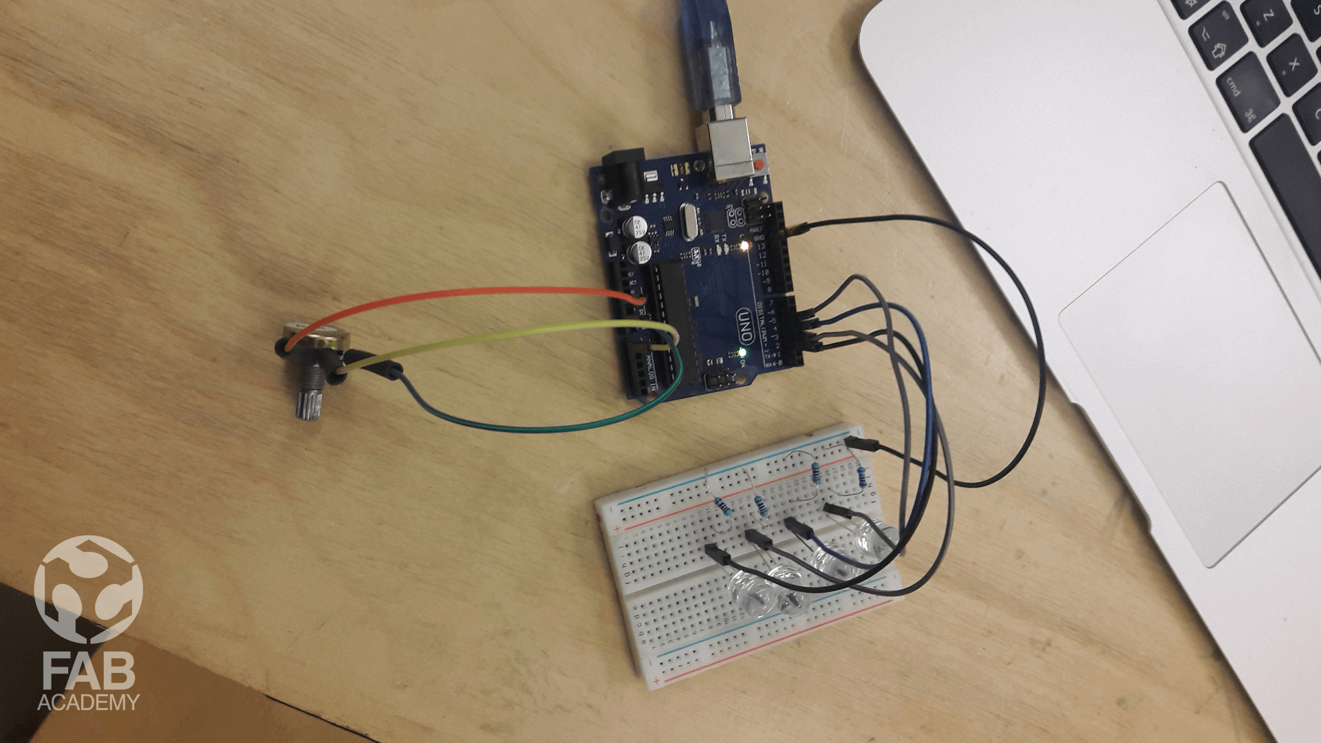
For my input devices week I wanted to work on a project that I can relate to my final project later on for this reason I decided to make led bar graph that I can control by a potentiometer.
To start working on this assignment first I decided to prototype the idea before moving to the board and schematic design so first
used an Arduino UNO board as a tool for prototyping and I followed this online tutorial.
As mentioned in the tutorial link that the board is connected to 10 Leds lights but since I had to apply the same schematic design on Attiny44 I later on decided to used 4 leds only since it has limited amount of pins. However, After I was done with prototyping and testing the idea with Arduino board as shown in image # 01 I started working on the schematic and board design using eagle.
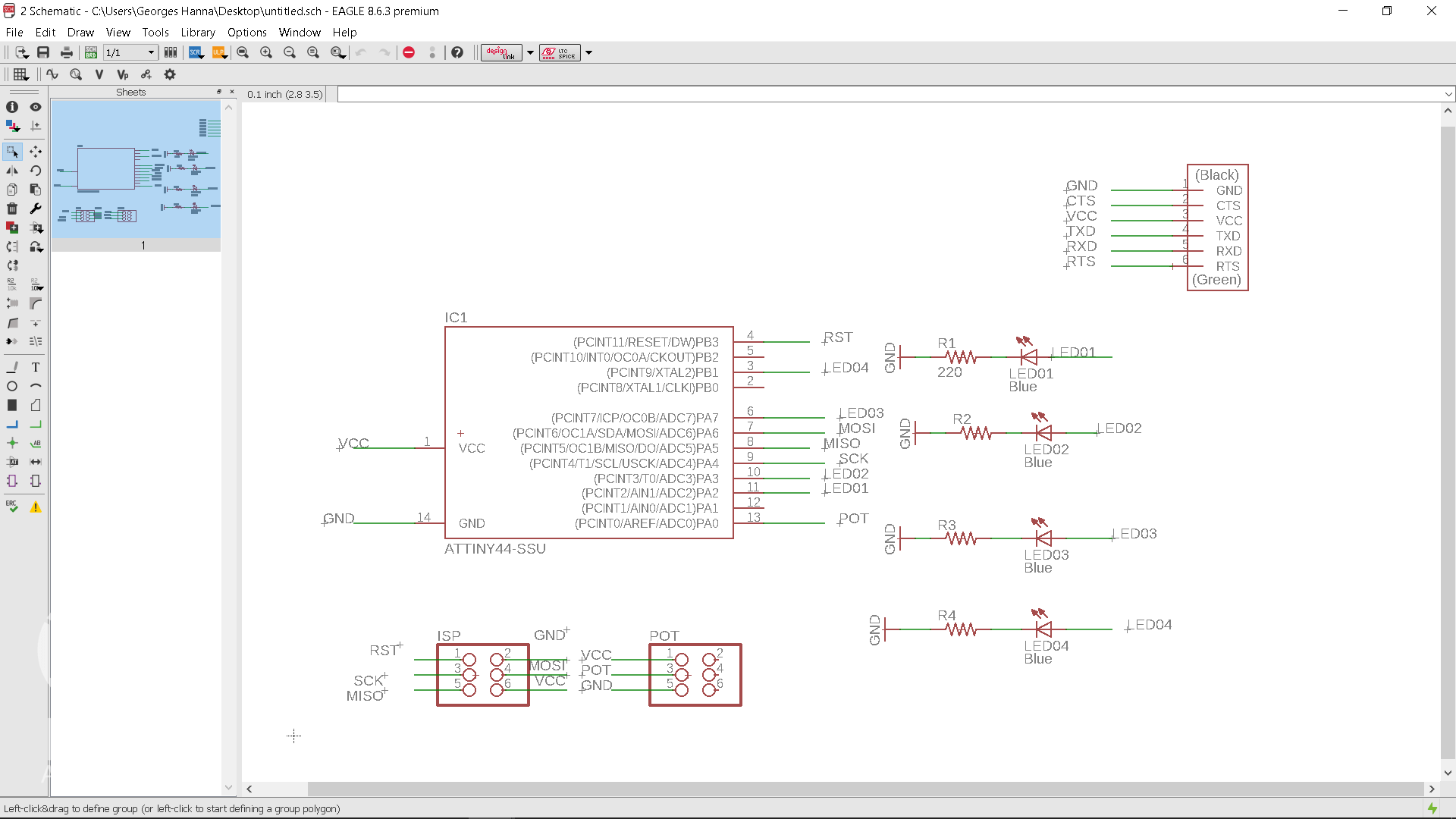
SCHEMATIC & BOARD DESIGN
To start working on the schematic design first I imported all the components needed as shown in image # 02
You can access all the components by clicking on ADD button that is shown on the left menu and then I wired all the components together based on the initial Arduino prototype I made.
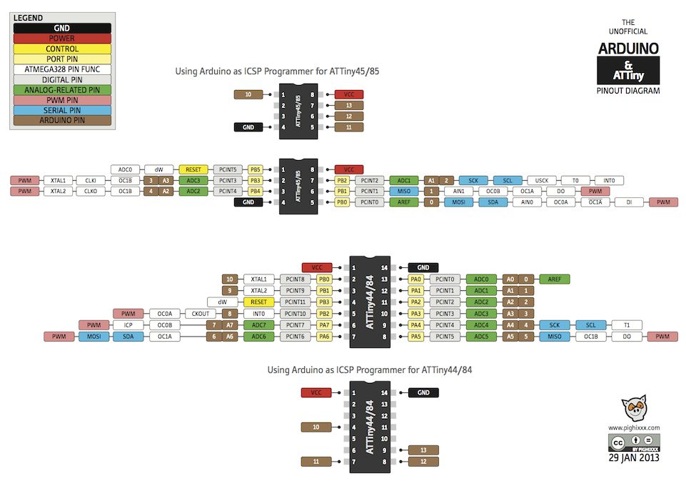
Note : In order to apply the same circuit design on the Attiny 44 microcontroller I followed the reference diagram that is shown in image # 07 to better understand the pin mapping .
After that I moved to the challenging task which was the board design.
• You can access the board design by going to menu > File > switch to board
For making the board I had mainly 2 options either to draw the traces manually or by using autoroute tool for me I decided to go for the 2nd option.
The first thing I did was moving the parts apart not close to each in order to give enough room for the traces to go between the parts and this would give me also enough space for soldering the components.
For moving the parts I used move tool .
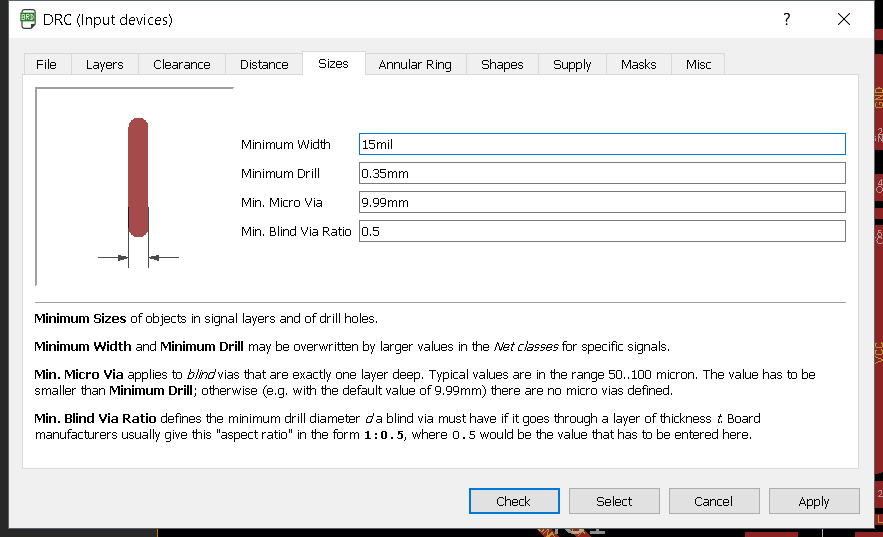
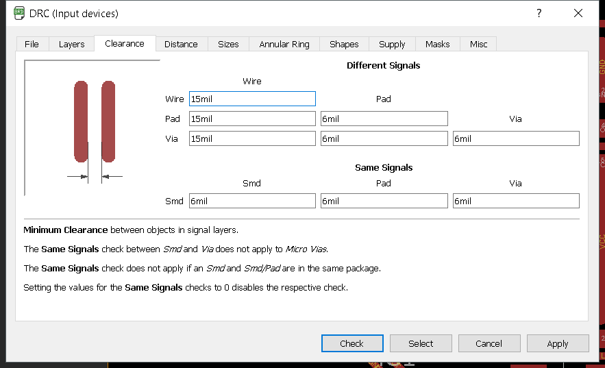
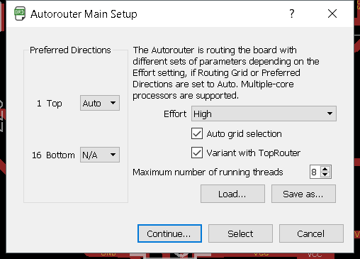
After that in order to be able to control the width of the traces and how much far the traces are from each other I had to adjust the design rule settings to access DRC menu I chose DRC from the tool menu and I applied the same settings that are shown in images #03 and #04
For the trace size I chose 15 mil since it matches the milling bit I was using which was 30 degree PCB engraving bit.
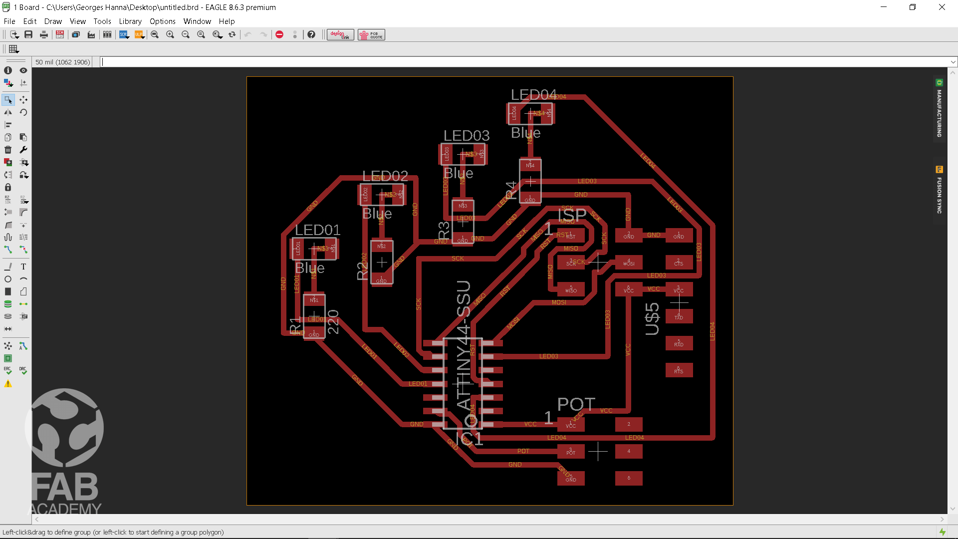
And then once I was done with adjusting the settings I clicked on Autorouter tool which is located in the tool menu and from the autorouter menu I chose auto from the top section since I am using single layer PCB as for the bottom section I chose N/A from the menu and I chose high from the effort down list menu after that I clicked on continue button a window called routing variant dialog appeared and then I clicked on start button in order to tell eagle to start computing the traces however after a few minutes of running many attempts eagle was able to draw the traces successfully and then I clicked on end job button.
After that I had to export the traces that was generated so to do that I turned off all the layers off from the visible layer menu except the top layer I left it on and from the file export menu I chose image
The export image window appeared and from that window I checked monochrome and I adjusted the resolution to be 600 DPI and then I chose to save the file in png file format so I can open it later on in fabmoduel and I clicked ok.
Then after the png file was generated I moved to the pcb milling process and then I soldered all the components .
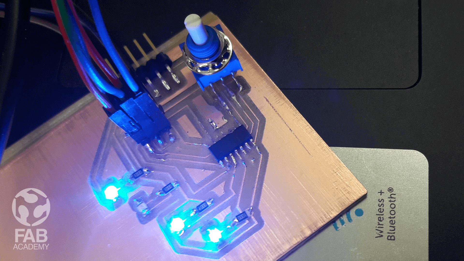
Technically speaking The process of developing the board was the same as in the previous weeks the only difference was that I was building this board from scratch and for me it was really challenging process. However after soldiering the parts the board was ready to be programed, For programing the board I used Arduino as a programmer and I followed exactly the same steps in the previous week embedded programing page however after uploading the code everything worked correctly except the 3thd led was not turning on as shown in image # 09 .
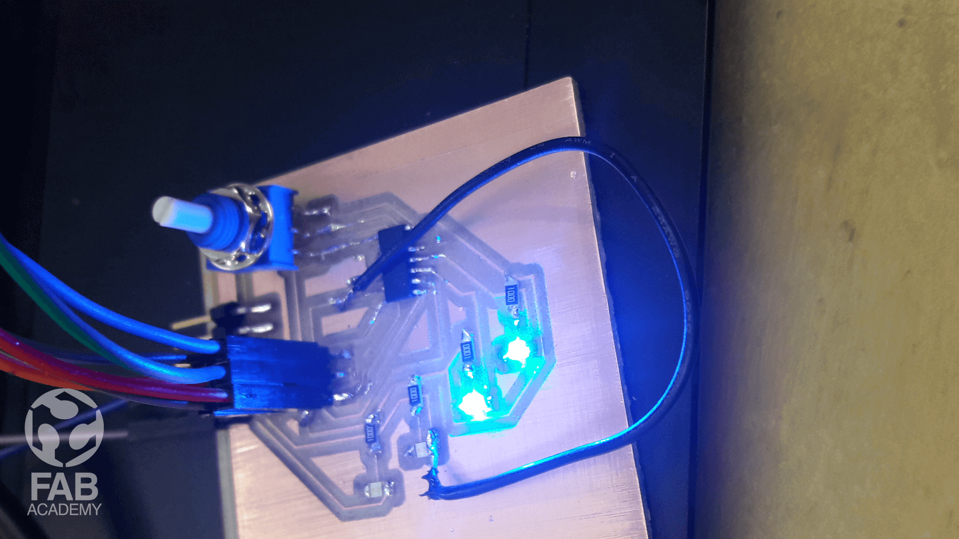
However, after checking the trace that is connecting the led with the Attiny44 I found that the trace is broken and in order to fix that issue I just used a wire jumper as shown in image #07 as a result the led started working perfectly without any problem as shown in the video.
Below is a list of the components I used
1 X Attiny44
4 X SMD LED
4 X 1000 ohm resistor
2 X [2x3] pins.
1 X FTDI pins
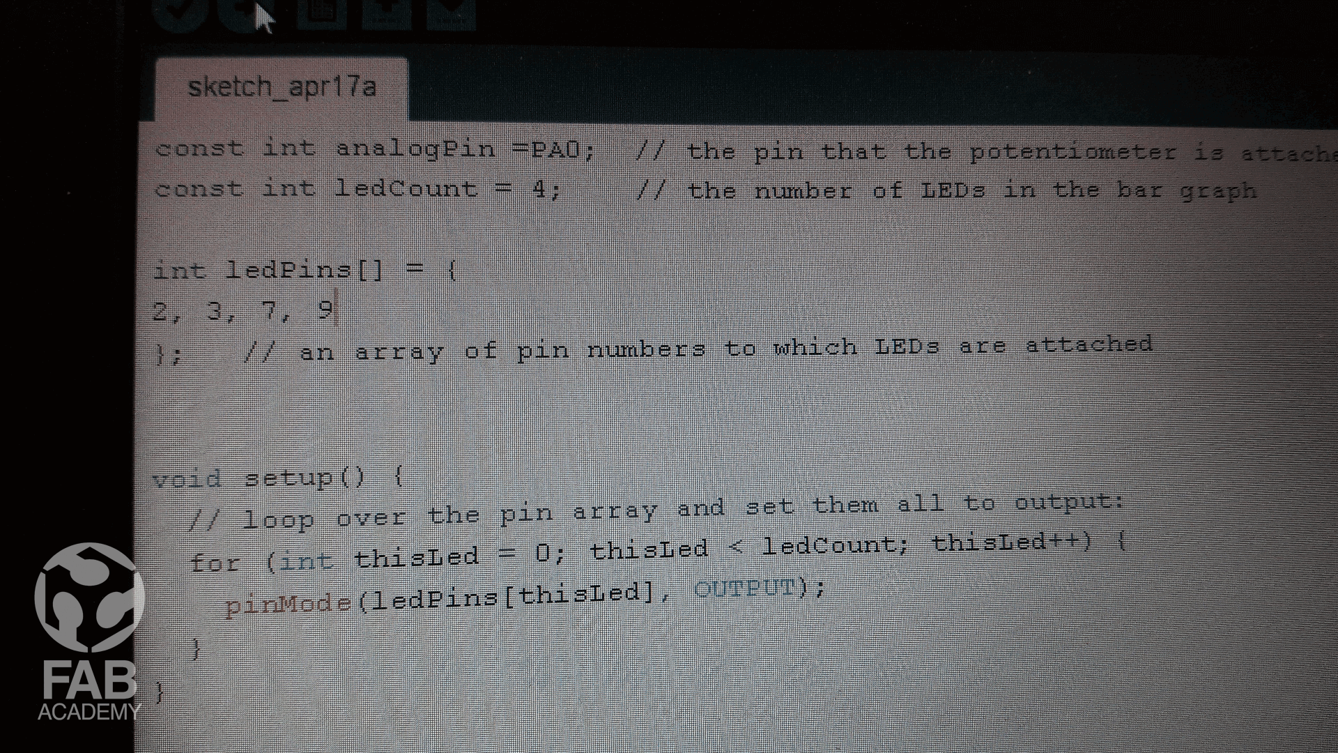
Below is the code I used :
/*
This code was modified by Georges Hanna Fab Academy 2018, INPUT DEVICES

The code was modified Based on the below codes :

  LED bar graph

  Turns on a series of LEDs based on the value of an analog sensor.
  This is a simple way to make a bar graph display. Though this graph uses 10
  LEDs, you can use any number by changing the LED count and the pins in the
  array.

  This method can be used to control any series of digital outputs that depends
  on an analog input.

  The circuit:
  - LEDs from pins 2 through 11 to ground

  created 4 Sep 2010
  by Tom Igoe

  This example code is in the public domain.

  http://www.arduino.cc/en/Tutorial/BarGraph
*/

const int analogPin = PA0; // the pin that the potentiometer is attached to
const int ledCount = 4; // the number of LEDs in the bar graph
int ledPins[] = {
2, 3, 7, 9
}; // an array of pin numbers to which LEDs are attached
void setup() {
// loop over the pin array and set them all to output:
for (int thisLed = 0; thisLed < ledCount; thisLed++) {
pinMode(ledPins[thisLed], OUTPUT);
}
}
void loop() {
// read the potentiometer:
int sensorReading = analogRead(analogPin);
// map the result to a range from 0 to the number of LEDs:
int ledLevel = map(sensorReading, 0, 1023, 0, ledCount);
// loop over the LED array:
for (int thisLed = 0; thisLed < ledCount; thisLed++) {
// if the array element's index is less than ledLevel,
// turn the pin for this element on:
if (thisLed < ledLevel) {
digitalWrite(ledPins[thisLed], HIGH);
}
// turn off all pins higher than the ledLevel:
else {
digitalWrite(ledPins[thisLed], LOW);
}
}
}
DOWNLOAD SECTION
+ INPUT WEEK BOARD DESIGN.sch DOWNLOAD .
+ INPUT WEEK BOARD DESIGN.brd DOWNLOAD .
+ INPUT_DEVICES.ino DOWNLOAD .